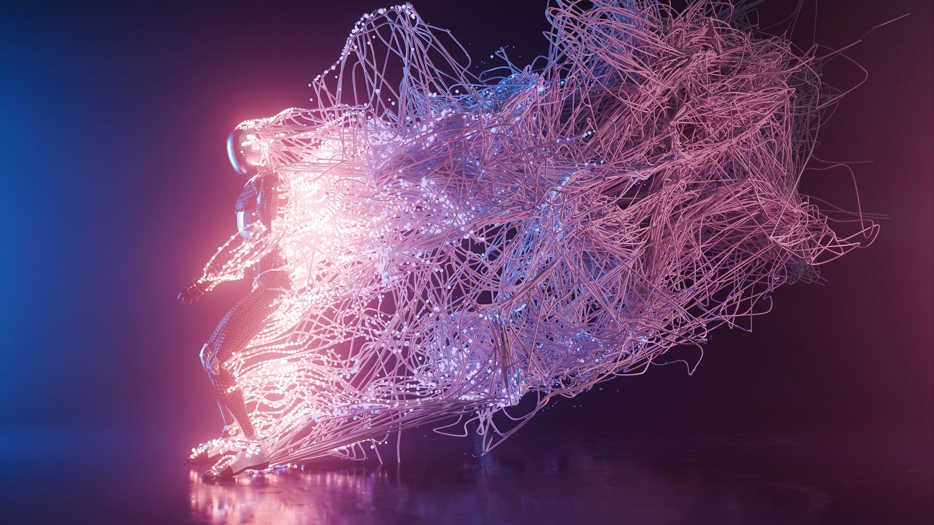
There are features in Blender that users have been waiting decades for. Light linking is one of them, even if users of other programmes find it hard to believe. For Blender users, however, this really is a new feature that Cycles has been given. We want to try it out together with the particle system from Simulation Nodes, which we built in issue 23:04|05. But first we’ll add another new feature to Blender 4.0, namely the ability to connect points with curves. The result adorns the cover of this issue.
No longer quite (so) tight
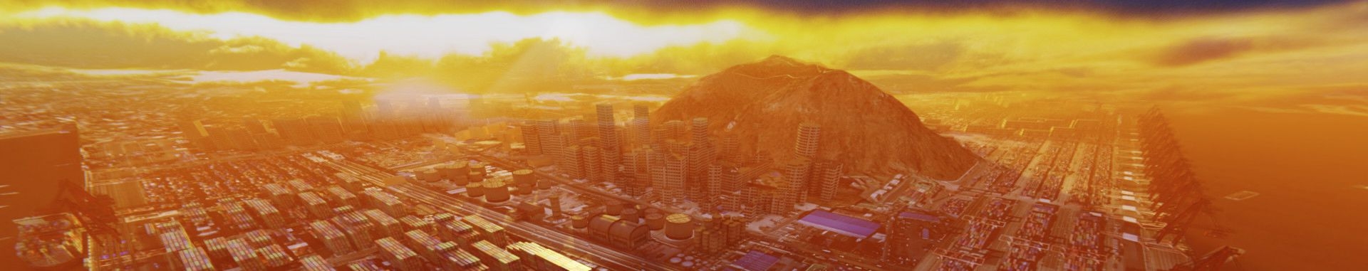
First download the result of the simulation nodes workshop and open the file – is.gd/simstrings. If you start the animation with the space bar, you will notice how close together the particles are. A tube is to be laid through each of these particles later, which would only result in a lump with this quantity. Therefore, first reduce the density in the modifier panel to 100.
The seed has to go
The particles are now much less dense. So that we can make threads out of them later, they should not appear randomly on the surface of the object, but always in the same place. This allows us to create a thread-like look even without the conversion to curves. Go to the geometry node workspace and make sure that the “Fire Particle System” node tree is open in the geometry node editor. Look for the “Distribute Points on Faces” node at the bottom left of the node tree and remove the connection in the seed socket. If you now play the animation, the particles look like strings of pearls that slowly disintegrate. Instead, you can move the seed to the outside as a parameter in the modifier panel by dragging it into the empty socket of the group input node.
Points to curves
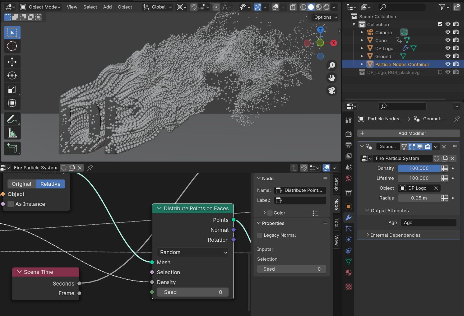
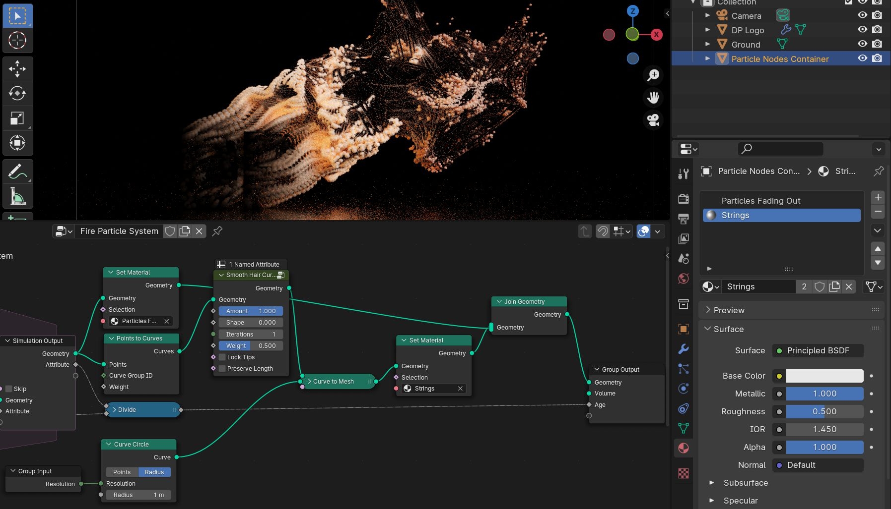
At the other end of the node tree, the generated points flow out of the “Simulation Output”. At this point, we can convert them to curves. Add a new node Points -> Points to Curves and connect it to the Geometry output of the Simulation Output node and the Geometry input of the Group Output node. Threads now appear in the viewport instead of points. We leave the Set Material node in the tree; we can still use it later to make the particles appear additionally.
Curves to meshes
The curves now appear in the viewport, but not yet in the render, as they do not yet have a surface. This is ensured by the Node Curve -> Operations -> Curve to Mesh. Set this between Points to Curves and Group Output. The curve has now become a mesh, but this consists of individual edges. For a proper surface, we need another curve for the profile. Click on the Profile Curve socket and drag out a new connection. A search field appears when you release the mouse pointer. Here you search for a circle, it is sufficient to enter “ci”, thanks to Type Ahead Find, Curve Circle -> Curve already appears in the second field, which you select. A new node now appears, which creates a circle that then acts as a profile for the curves created from the particles.

Resolution
There is now a lot going on in the viewport, as suddenly a huge amount of geometry wants to be displayed. You can put a stop to this by reducing the resolution in the curve circle node to eight. But perhaps you want to reduce the resolution a little further when experimenting and then increase it again during the final rendering? Switching to the Geometry Node workspace each time and searching for the right node in the Node Editor may not be the most skilful way to do this. It is therefore a good idea to move this parameter to the outside of the modifier UI. Drag out a new node connection as you have just done and search for Group Input. A Group Input node appears, in which all sockets are hidden except for the newly created resolution. The Blender interface is full of little surprises that make everyday work easier.
Node Group Assets
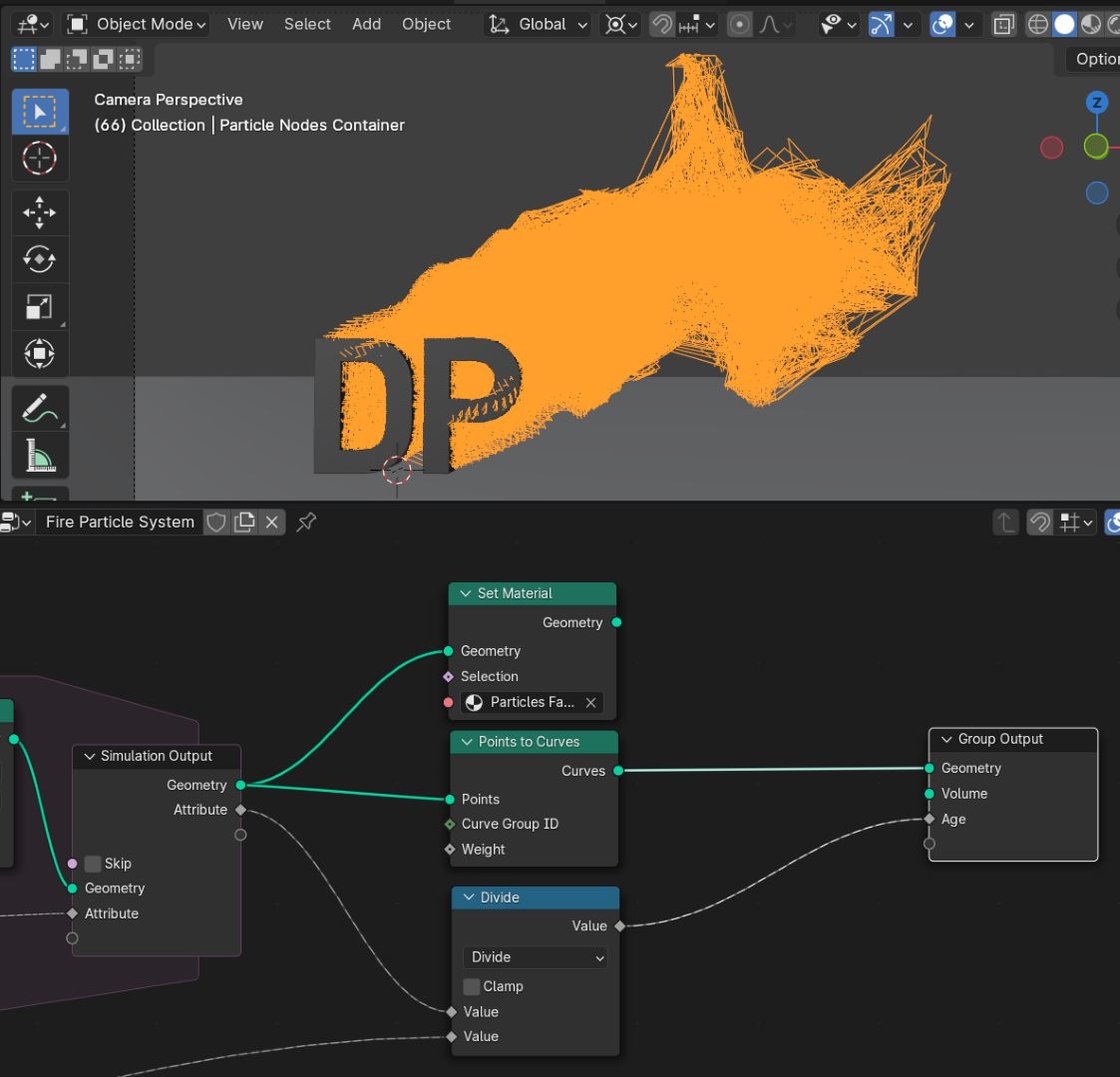
The curves are currently very sharp on each particle, which has a negative effect on shading and may not be the style everyone wants. We need something to round them off like the subsurf modifier for meshes. Such a tool is now supplied in Blender as a Node Group Asset with the new hair assets. We take advantage of the fact that hair and curves are almost the same thing in Blender, the corresponding assets actually all work on curves. So we can also use them with our setup. Add a node Hair -> Deformation -> Smooth Hair Curves and place it between Points to Curve and Curve to Mesh.
The wild curves
The result should look pretty wild, none of the curves are in place anymore. This is due to the Preserve Length setting. Switch this off and our threads are all back in the right place, albeit slightly rounded. You can use the iterations to determine how strong the effect should be. One was enough for our cover, the more you use, the more rounded the curves become.
Bringing back the particles
As we are already simulating the movements of a particle system for the threads anyway, we can use them at the same time by representing them as points again. For this purpose, we have not deleted the Set Material node earlier in the article, but merely separated it. Add a Node Geometry -> Join Geometry between Curve to Mesh and Group Output. Also connect the output of the Set Material node to the Join Geometry node. The particles now appear as point objects in the viewport and should already have the appropriate material in the render preview.
Steel tubes
To give the threads a material as well, add another material slot to the Particle Nodes Container object and create a new material there with metallic at 1.0. However, it must first be assigned in the Geometry Nodes so that it also appears on the tubes. Duplicate the Set Material node and place it between Curve to Mesh and Join Geometry. The threads should now appear very dark again. This is due to a special feature of the source file. In this file, the world is invisible to glossy shaders, which produces an interesting effect, as the points in the shader have a diffuse component and therefore appear as if they themselves are glowing, although not as evenly as would be the case with emission without tricks.
Light Linking
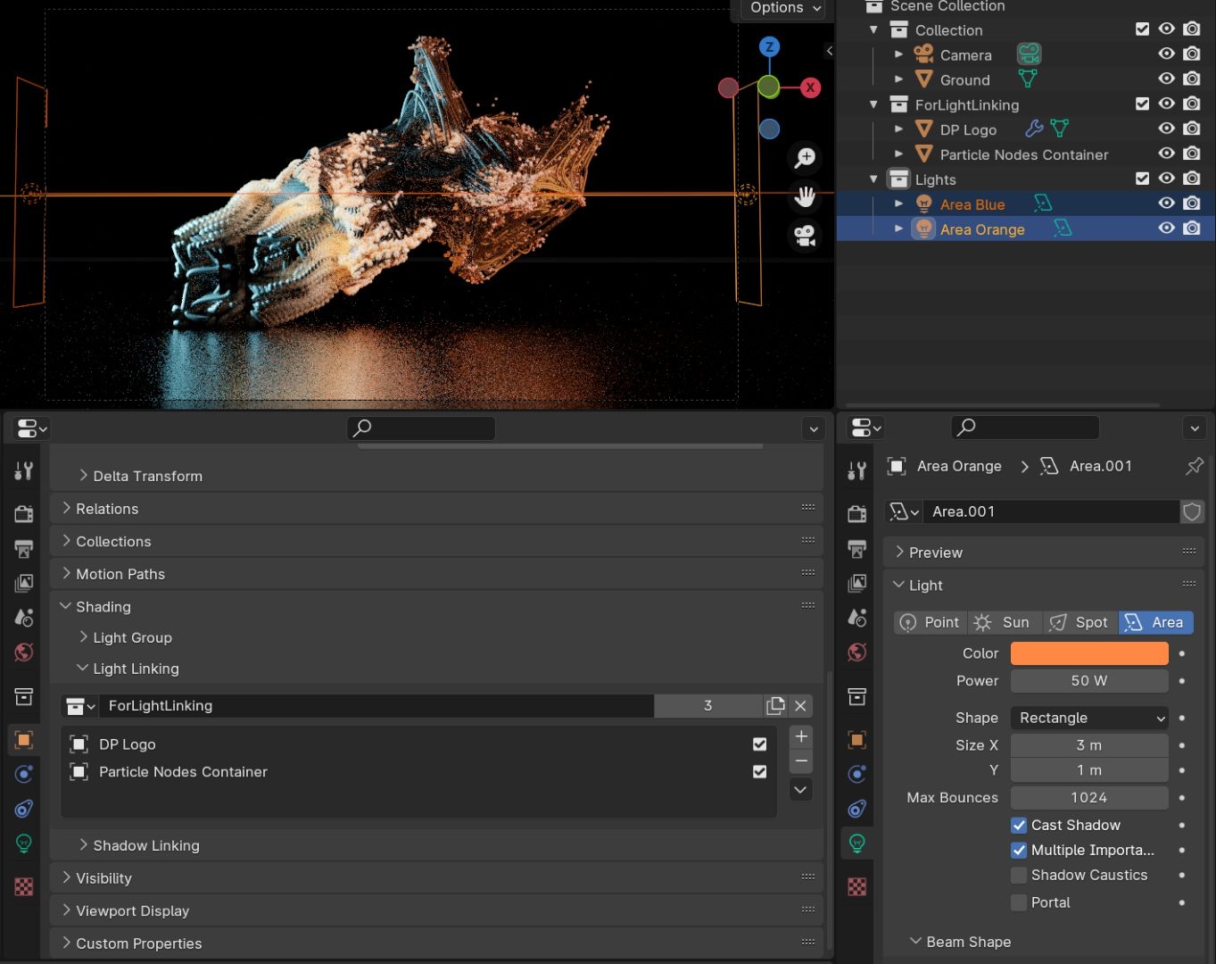
The fact that the world is not visible in shiny reflective surfaces is a simple version of light linking and has been present in Cycles from the very beginning. However, this is shader-based and therefore very generalised. In Blender 4.0, it is now possible for the first time to limit the influence of light sources on objects in a collection. And we would now like to use this to illuminate the threads of two area lights on the left and right, and only the threads, particles and logo, but not the floor. To do this, create a new collection in the Outliner and drag the DP logo and the Particle Nodes container into it.
Orange and Teal
Then create another new collection and two area lights in it, whose shape you set to Rectangle in the Object Data Properties and set Size X to 3.0. Align the two area lights so that they shine on the scene from the left and right and give them two contrasting colours, e.g. the famous combination of orange and aquamarine. You should set the cold light source to a much stronger colour than the warm one, e.g. 200 watts and 50 watts.
Still well hidden
To restrict the illumination of the two area lights to the logo, particles and threads, you must select the collection in which the three objects are located for both in the object properties in the shading panel under Light Linking. Now you no longer illuminate the floor, which draws the viewer’s attention to the particle action.
Fade-in also for threads
However, there is one last detail I would like to mention. The particles fade in our example file because we built our particle system in the last workshop so that it saves the age of each point as a value between 0.0 and 1.0. We can also access these values for the threads. In other words, the curves can also be threaded in and out.
Mastered with flying colours
Go to the Shading Workspace and select the Particle Nodes Container object. Select the Particles Fading Out material in the material slots and select the three connected nodes Attribute, Invert Colour and Colour Ramp in the Shader Editor. Copy them using Ctrl C, then select the material that you have given to the threads, or press Ctrl V in the Shader Editor. Now that you have copied the nodes, connect the output of the Colour Ramp node to the alpha socket of the Principled BSDF. The curves will now appear and fade and you have mastered the technical part of the workshop with flying colours.
Let off steam
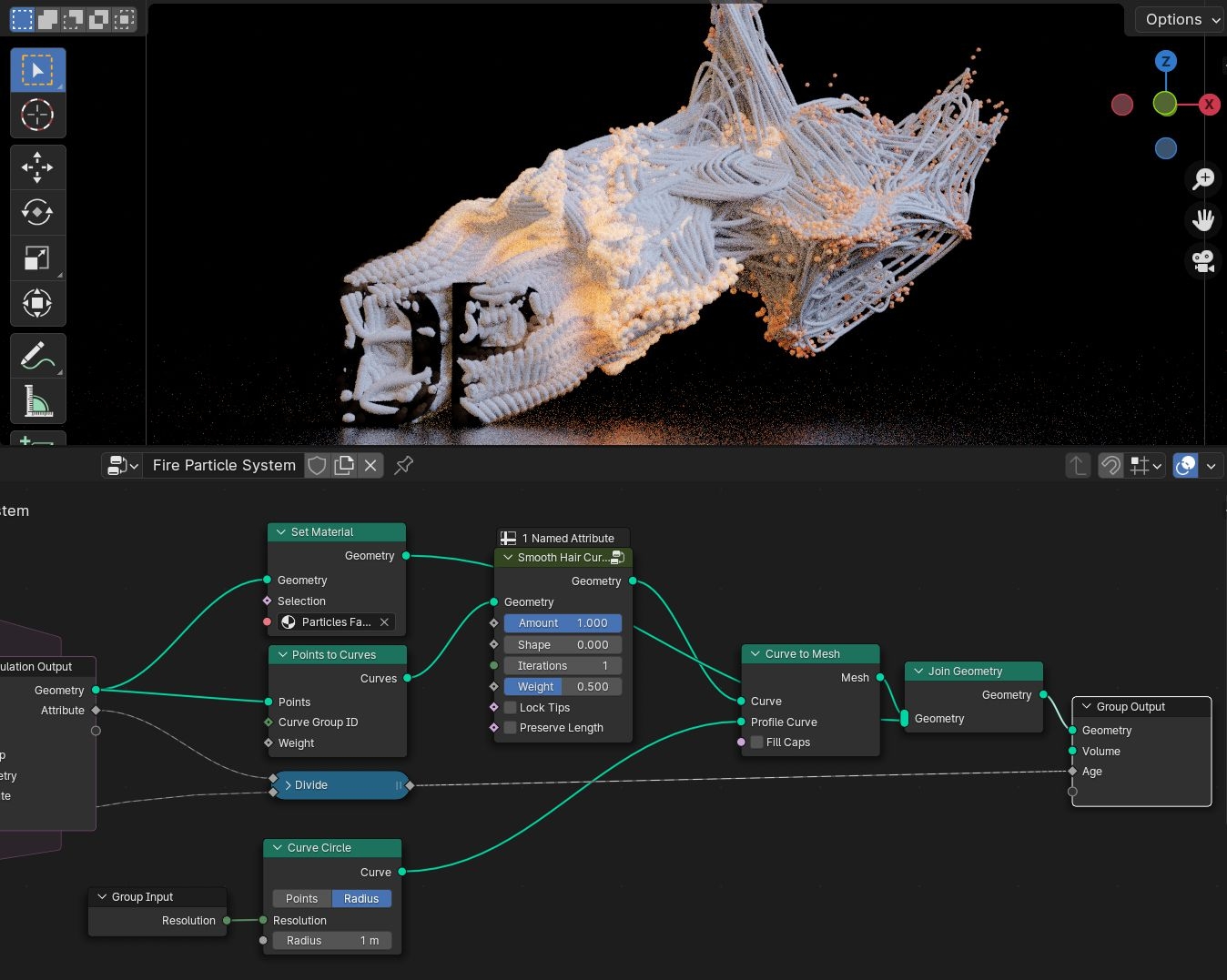
Now it’s time to let off steam. For the cover image, I have changed the direction of movement of the particles upwards. You can also change the direction in the Vector Add Node in the Simulation Zone. And at this point, think about how you could make the structure even more user-friendly. For example, by also exposing the direction of movement. Or adding an auxiliary object that specifies the direction and “wind force”?
Conclusion and outlook
Blender 4.0 brings some new features, including the eagerly awaited Light Linking and new Geometry Nodes. Both were combined in this workshop. But there are possibilities to go further. For example, the threads are currently generated at each frame like tangles; with a few more nodes, they could be displayed like a string of particles or like growing hair, quasi perpendicular to the current direction. This method is particularly suitable for motion capture recordings, as it allows a motion path to be created for any point on a character. I used this method for the Udon asset for the RADiCAL blender add-on. RADiCAL is a service for extracting motion data from simple video recordings or livestreams.