



Placement in the Pipeline and the Ecosystem: For those who don’t know the tool: InstaMAT is Abstract‘s material and asset creation platform, combining procedural Element Graphs, layering and painting with pipeline automation. Official integrations connect InstaMAT to Autodesk Maya, Autodesk 3ds Max, Blender, Unity and Unreal Engine, while the wider developer stack includes command-line pipeline automation and a C++ SDK.
A scatter node, not a rock simulator
Abstract’s latest rock-scattering tutorial concentrates on the Guided Scatter node inside InstaMAT. The important production distinction is what the node actually scatters. Guided Scatter lives in the Effects/Scatter category and operates on image data. It distributes image tiles and associated normal information, then returns an output image, a normal image and a Floodfill image. It is not a geometry-instancing system that drops polygonal boulders around an Unreal level or a Maya environment. The rocks in the demonstration are procedural texture elements.
Guidance instead of pure variance
InstaMAT’s Tile Scatter already provides a broad randomised scattering system. It accepts multiple image and normal inputs, supports an atlas input, offers orientation and size variance, collision masking, several pattern shapes and different blending modes. Guided Scatter extends that concept by exposing additional images that can steer properties instead of leaving those properties primarily to fixed values and random variance.
The current Guided Scatter reference exposes nine regular image inputs and nine corresponding normal inputs, plus atlas, alpha and background inputs. Separate controls can activate guidance maps for mask, colour, offset, scale, orientation, vector, height and alpha behaviour. The node also exposes filtering, mip-range and multisampling controls, colour blending, normal handling, pattern settings and collision parameters. In other words, it is less “sprinkle some rocks” and more “define the bureaucratic framework under which each rock may legally exist.”
Boulders outside, pebbles inside
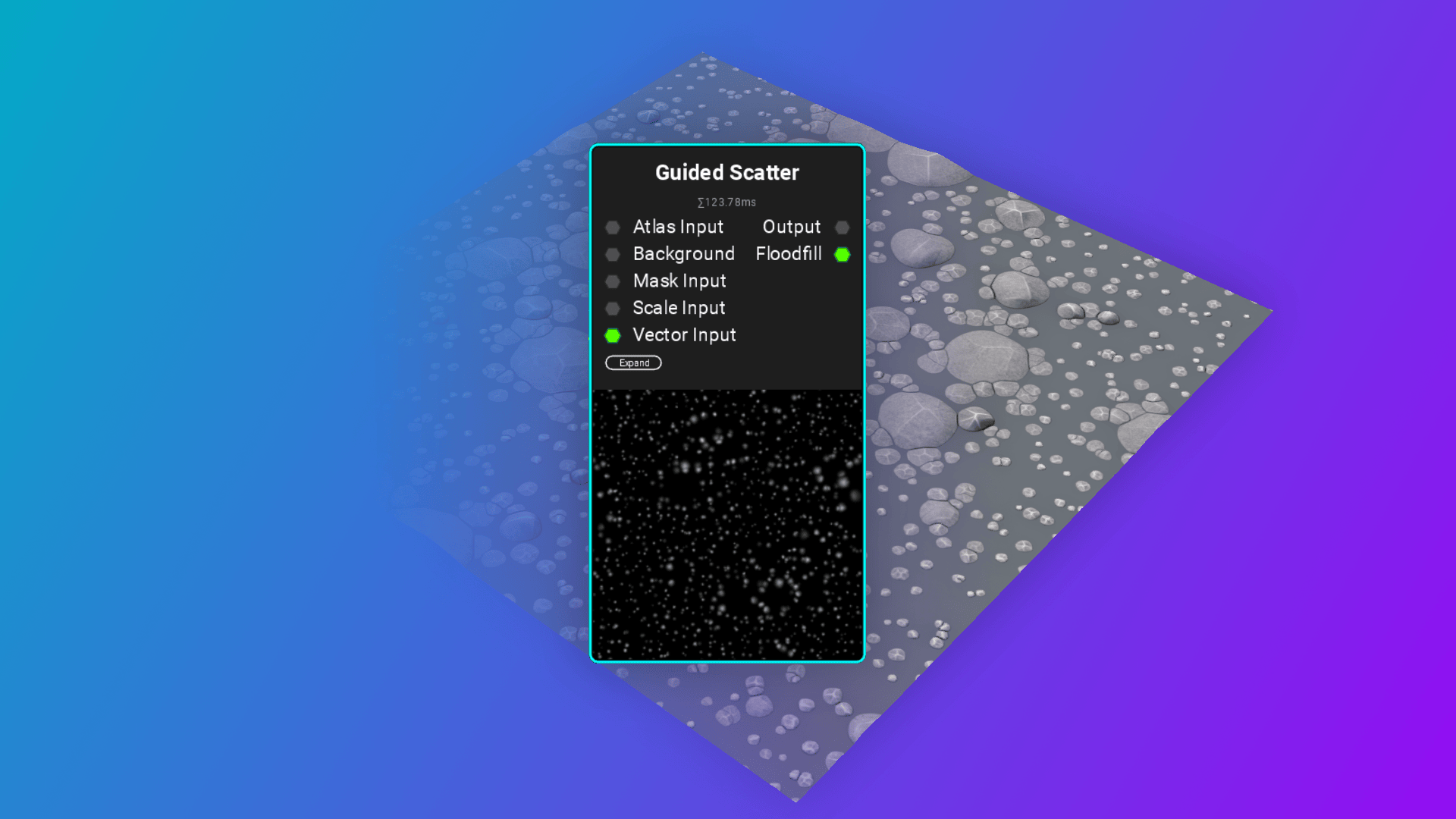
Abstract’s tutorial demonstrates a practical reason for all those inputs. The graph layers smaller rocks around larger formations, using masks and scale guidance to vary the apparent size of scattered elements. Large forms can occupy open regions while smaller fragments accumulate in tighter areas. The tutorial also combines atlas inputs with pattern adjustments and shape refinement instead of relying on one repeated source tile.
Guided Scatter exposes Mask Density, threshold and collision controls, including configurable collision sampling and collision scale. Scale can be controlled globally or through grayscale scale maps, while orientation receives its own input and factor. A Vector Input goes further by providing factors for rotation, scale and offset. This is an artist-facing control system built around ordinary procedural map data, so noise functions, painted masks or outputs from earlier graph stages can become distribution instructions for later ones.
The production advantage is repeatability. Instead of painting every cluster manually, artists can encode placement logic into the graph and regenerate it when upstream material parameters change. That can be particularly useful for terrain materials, rubble, aggregate surfaces, roof treatments or other materials where recognisable repetition is expensive visually but manual placement is expensive in people. The usual procedural bargain still applies: you exchange hand labour for graph complexity.
The node’s direct outputs remain texture-oriented: Output Image, Normal Image and Floodfill Image. The Floodfill result is particularly useful when subsequent operations need per-element regions for gradients, randomisation or masks. Normal-aware scattering also lets the graph carry surface-direction information alongside the visual pattern instead of reconstructing every detail afterwards.

Enterprise trust
By the way: In August 2026, Abstract announced that it had completed SOC 2 compliance work covering the systems behind InstaLOD, InstaMAT, Polyverse and RSX Engine. The company says an independent auditor examined evidence around system access, data handling, policies, incident response, vendor risk, logging and monitoring. For studios using Abstract technology in asset pipelines or enterprise infrastructure, the relevance is procurement rather than better-looking rocks: documented security controls can become a prerequisite when production data, cloud services or automated systems cross corporate boundaries. AICPA defines SOC 2 reporting as an examination of controls at a service organisation relevant to security, availability, processing integrity, confidentiality or privacy. Abstract’s announcement is here
https://abstract3d.com/2026/08/06/earning-trust-the-hard-way-abstract-earns-soc-2-certification/
Topics
 Autodesk 3ds Max583 postsBuild scenes with a well-stocked digital toolbox. Explore 3ds Max modelling, visualisation and rendering workflows, alongside updates and techniques for turning geometry into characters, environments and carefully composed images.
 Blender699 postsA whole creative workshop behind one orange mark. Explore Blender news and techniques across modelling, animation, effects and rendering, with workflows for taking an idea from an empty scene to a finished image.
 Unity99 postsSet a scene, then give it something to do. Explore Unity software, realtime graphics and interactive production workflows, from asset preparation to the systems that make a digital world respond.
 Unreal Engine513 postsWalk into the scene while it is still taking shape. Explore Unreal Engine realtime rendering, virtual-production and world-building workflows that bring immediate visual feedback into increasingly varied creative projects.
Article details
- Published
- Author
- Bela Beier
- Reading time
- About 4 min
- Word count
- 683